Hello. Hoping you can help here. There is big business in Europe with tools that can read and write to the Bosch Tricore based EDC15/16/17 ecus. They seem to use jtag and a power wire direct to cpu pin.
Have you played with Tricore cpu at all?
Infineon Tricore Bootmode
-
Decryptor
- Junior Member
- Posts: 26
- Joined: Thu Nov 29, 2007 10:08 pm
Yes there are some tools for 1000+ dollars and some clones of those tools for 250-700. Depending on if made in EU or china.
If someone made a low priced decent quality tool for this purpose it would sell well, just based on how many knockoffs there are.
https://www.youtube.com/watch?v=iuQ8GZc3HE0
If someone made a low priced decent quality tool for this purpose it would sell well, just based on how many knockoffs there are.
https://www.youtube.com/watch?v=iuQ8GZc3HE0
-
Decryptor
- Junior Member
- Posts: 26
- Joined: Thu Nov 29, 2007 10:08 pm
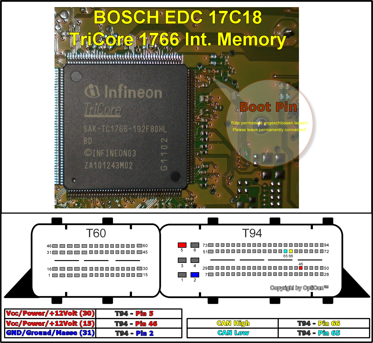
http://wiki.obdtuning.com/images/6/6d/Opel_EDC17C18.jpg
just a different way to use same circuit I guess. Lots of people buy the big aluminum positioning devices and BDM plugs that have little mini pcbs for specific ecus to provide a way for trained monkey to use it.
This pinout is showing the boot pin and then the power/ground/data on the actual ecu connectors.
-
usbbdm
- Junior Member
- Posts: 8982
- Joined: Mon Jul 18, 2005 9:33 pm
Can you tell me what is the purpose of boot pin? How to connect boot pin?Munchies wrote:http://wiki.obdtuning.com/images/6/6d/Opel_EDC17C18.jpg
just a different way to use same circuit I guess. Lots of people buy the big aluminum positioning devices and BDM plugs that have little mini pcbs for specific ecus to provide a way for trained monkey to use it.
This pinout is showing the boot pin and then the power/ground/data on the actual ecu connectors.
I have similar issue with Audi ECU.
-
Decryptor
- Junior Member
- Posts: 26
- Joined: Thu Nov 29, 2007 10:08 pm
http://www.evc.de/en/product/bsl/
"To put the processor into the bootmode a modification on the printed circuit board is necessary. This modification depends on the type of the processor and so the type of the ECU. In the most simple case one pin of the processor must be connected to ground. Therefore a contact needle with a wire and a tripod is attached to the system. The wire must be connected to the BSL130.L probe."
I find lots of discussion regarding it be a ground to activate 'boot mode'.
http://www.intron-tech.com.cn/downfile% ... S_V1.3.pdf
Look. Guy here charge 1300 euro for similar tool. its crazy. https://www.avtotools.com/shop/index.php?productID=411
-
Decryptor
- Junior Member
- Posts: 26
- Joined: Thu Nov 29, 2007 10:08 pm
-
Decryptor
- Junior Member
- Posts: 26
- Joined: Thu Nov 29, 2007 10:08 pm
The TC1767 On-chip Debug Support (OCDS) provides a JTAG port for
communication between external hardware and the system.
2.5.4 Tool Interfaces
Three options exist for the communication channel between Tools (e.g. Debugger,
Calibration Tool) and TC1767:
• Two wire DAP (Device Access Port) protocol for long connections or noisy
environments.
• Four (or five) wire JTAG (IEEE 1149.1) for standardized manufacturing tests.
• CAN (plus software linked into the application code) for low bandwidth deeply
embedded purposes.
• DAP and JTAG are clocked by the tool.
• Bit clock up to 40 MHz for JTAG, up to 80 MHz for DAP.
• Hot attach (i.e. physical disconnect/reconnect of the host connection without reset of
the TC1767) for all interfaces.
• Infineon standard DAS (Device Access Server) implementation for seamless,
transparent tool access over any supported interface.
• Lock mechanism to prevent unauthorized tool access to critical application code.
-
Decryptor
- Junior Member
- Posts: 26
- Joined: Thu Nov 29, 2007 10:08 pm
Who is online
Users browsing this forum: No registered users and 1 guest